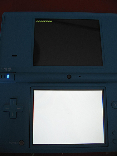
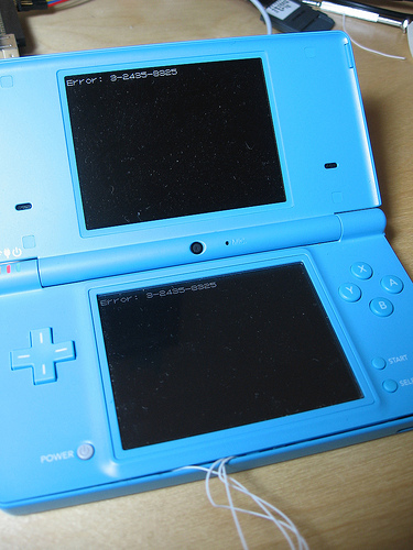
Stage2: Difference between revisions
→Stage 2: renamed 10-letter "binblksize" to 20-letter "binblk->binblocksize", please correct if that was wrong |
|||
| Line 161: | Line 161: | ||
Whereas the filesystem data in NAND is encrypted using a unique key for every DSi, the stage2 bootloader is identical on every DSi tested so far. The stage2 bootloader binaries are not encrypted with any console-unique keys. | Whereas the filesystem data in NAND is encrypted using a unique key for every DSi, the stage2 bootloader is identical on every DSi tested so far. The stage2 bootloader binaries are not encrypted with any console-unique keys. | ||
Stage1 uses the [[AES_Engine]] to decrypt each ARM9/ARM7 binary, where keyY is from the above signature. The [[AES_Engine]] keyslot used here is the same one used for the shared areas for [[Tad]], therefore the keyX is the same as the one used for that. The following is used for the CTR, where "binblk->binblocksize" is the above binary size aligned to 0x200-bytes: | Stage1 uses the [[AES_Engine|AES CTR]] to decrypt each ARM9/ARM7 binary, where keyY is from the above signature. The [[AES_Engine]] keyslot used here is the same one used for the shared areas for [[Tad]], therefore the keyX is the same as the one used for that. The following is used for the CTR, where "binblk->binblocksize" is the above binary size aligned to 0x200-bytes: | ||
unsigned int ctr[4]; | unsigned int ctr[4]; | ||
Revision as of 22:46, 20 April 2015
Stage 1

The first stage of the DSi's bootloader lives in ROM, presumably on the CPU die. It loads further encrypted+signed stages from NAND flash, starting with a plaintext offset table in the sector at offset 0x200.
Not much is known about this bootloader yet, but it presumably knows how to:
- Initialize the encryption hardware
- Read the contents of NVRAM
- Initialize both LCDs
- Read blocks (but not files) from the NAND flash
- Perform some variety of integrity check on all data it reads (signature, CRC, ?)
- Display basic hexadecimal error codes
- Possibly factory-programming the NAND flash?
- Might also do basic power-on self test of peripherals
Known error codes:
| Error Code | Description |
|---|---|
| 0000FE00 | Error communicating with NAND chip. (It's missing, CLK is shorted, etc.) |
| 0000FEFC | Integrity error in first block of Stage 2 (address at 0x220) |
| 0000FEFD | Integrity error in second block of Stage 2 (address at 0x230) |
| 0000FEFE | Boot sector integrity error (Sector 0x200 not valid), or error in NVRAM contents. |
Stage 2

Unlike the stage1 bootloader, which must be small enough to fit in ROM (probably several kilobytes), the stage2 bootloader has about a megabyte of NAND flash reserved for it. The stage2 bootloader understands partitions and filesystems, and it is capable of loading the DSi menu. It also must understand the encryption used on filesystem blocks in the NAND, and it must understand how to load and validate title metadata.
The Stage 2 loader was not modified by the System Menu 1.4 update. This is still earlier in the boot process than the "Health and Safety" warning(that warning is displayed by the sysmenu).
The first stage bootloader reads the sector at offset 0x200 in order to find a table of offsets to the Stage 2 bootloader:
00000220  00 08 00 00 10 64 02 00  00 80 7b 03 00 66 02 00  |.....d....{..f..|
00000230  00 6e 02 00 88 75 02 00  00 80 7b 03 00 76 02 00  |.n...u....{..v..|
00000240  00 00 00 00 00 00 00 00  00 00 00 00 00 00 00 00  |................|
This is describing two chunks of the stage2 loader: the ARM9-binary 0x26410 bytes in length at address 0x800, and the ARM7-binary 0x27588 bytes at address 0x26e00.
Structure of this header:
| Offset | Size | Description |
|---|---|---|
| 0x0 | 0x20 | Reserved (zerofilled) |
| 0x20 | 0x4 | ARM9 Bootcode, eMMC Source Offset |
| 0x24 | 0x4 | ARM9 Bootcode, Size "Actual binary size" |
| 0x28 | 0x4 | ARM9 Bootcode, RAM Destination Address and Entrypoint |
| 0x2C | 0x4 | ARM9 Bootcode, Size rounded up to multiple of 0x200 |
| 0x30 | 0x4 | ARM7 Bootcode, eMMC Source Offset |
| 0x34 | 0x4 | ARM7 Bootcode, Size "Actual binary size" |
| 0x38 | 0x4 | ARM7 Bootcode, RAM Destination Address and Entrypoint |
| 0x3C | 0x4 | ARM7 Bootcode, Size rounded up to multiple of 0x200 |
| 0x40 | 0xBF | Reserved (zerofilled) |
| 0xFF | 0x1 | Unknown, value 0xFF? (actually, this is appears to be always 0Ch, not FFh?) |
| 0x100 | 0x80 | RSA-1024 Data Block |
| 0x180 | 0x14 | Global MBK1..MBK5 Slot Settings |
| 0x194 | 0xC | Local MBK6..MBK8 Settings for ARM9 Side |
| 0x1A0 | 0xC | Local MBK6..MBK8 Settings for ARM7 Side |
| 0x1AC | 0x4 | Global MBK9 Slot Master Setting |
| 0x1B0 | 0x50 | Reserved (zerofilled) |
Note that the above format resembles the DSi Cartridge Header (entries 0x20-0x3F are roughly similar, and entries 0x180-0x1AF appear to be same as in cart header).
The RSA pubks(the one for 3DS and the other one for DSi) for the below signature can be obtained from 3DS TWL_FIRM Process9(this is required for getting the binaries' keyY). It's unknown(?) if the DSi bootrom(s) copy this modulo to anywhere outside of bootrom.
Structure of the 0x74-byte "hash-data" stored in the RSA message:
| Offset | Size | Description |
|---|---|---|
| 0x0 | 0x10 | AES_Engine keyY used for the ARM9/ARM7 binaries crypto. |
| 0x10 | 0x14 | SHA1 hash. Going by 3DS TWL_FIRM this seems to calculated over the first 0x28-bytes of NAND, then the first 0x100-bytes of the header, then the last 0x80-bytes of the header(following the signature). This works with the bootloader contained in TWL_FIRM, however it's unknown how the first part is handled on DSi. |
| 0x24 | 0x14 | SHA1 hash over the plaintext ARM9 binary, with the actual binary size. |
| 0x38 | 0x14 | SHA1 hash over the plaintext ARM7 binary, with the actual binary size. |
| 0x4C | 0x14 | Unknown, not used by 3DS TWL_FIRM. Normally all-zero. |
| 0x60 | 0x14 | Unknown, not used by 3DS TWL_FIRM. |
Note that this sector (and two similar ones at 0x400 and 0x600) appear to be the only unencrypted blocks on the NAND flash.
After loading+verifying the the above header, the ARM7 binary is loaded+verified, then the ARM9 binary is loaded+verified.
Whereas the filesystem data in NAND is encrypted using a unique key for every DSi, the stage2 bootloader is identical on every DSi tested so far. The stage2 bootloader binaries are not encrypted with any console-unique keys.
Stage1 uses the AES CTR to decrypt each ARM9/ARM7 binary, where keyY is from the above signature. The AES_Engine keyslot used here is the same one used for the shared areas for Tad, therefore the keyX is the same as the one used for that. The following is used for the CTR, where "binblk->binblocksize" is the above binary size aligned to 0x200-bytes:
 unsigned int ctr[4];
 memset(ctr, 0, 16);

 ctr[0] = binblk->binblocksize;
 ctr[1] = (unsigned int)(-binblk->binblocksize);
 ctr[2] = ~binblk->binblocksize;
Stage2 operations
After Stage 2 is loaded:
- The NAND flash is partially re-initialized
- Sector 0 is read from the NAND. This appears to be an (encrypted) DOS-style MBR.
- The MBR signature and the type of the first partition are verified.
- Filesystem metadata is read from sectors starting around 0x100000. The metadata is in FAT16 format with long filenames.
- Multiple files are loaded from the filesystem. The exact read addresses will vary depending on your DSi's firmware version and the state of its filesystem when you performed the last firmware update. On a brand new DSi, it appears that the DSi Menu itself is loaded from 0xb20000 after two small metadata files are read from 0xb1c000 and 0x7a0000.
All errors show before the health and safety screen. It appears that stage2 errors from a cold power-on always cause the DSi to hang at a black screen, whereas stage2 errors after reset (pressing but not holding the power button) will give an error message screen. Known errors:
| Text | Description |
|---|---|
| "Error: 1-2435-8325" | Invalid signature or partition type in MBR, invalid starting LBA. |
| "Error: 3-2435-8325" | DSi Menu integrity checks failed |